Electrical Lighting Circuit Diagrams - Intermediate Switch 3 Way Switch Connection Wiring Diagram Youtube - Wiring diagram since wiring connections and terminal markings are. (fig 2) the feed cable comes from a previous junction box or from the consumer unit, the red, black and earth wires are connected to separate… New rules have been introduced for electrical safety in the home, please read this document by clicking here, before starting any electrical work Phase, neutral and ground.all three conductors reach to the terminal point of each luminaire and if it has a metal chassis the ground should be connected in the appropriate position. Templates, tools & symbols to draft any electrical, wiring or circuit schematic. Each house should ideally have at least two lighting circuits;
A cable is run from the junction box to the light, usually via a ceiling rose. Duplex, gfci, 15, 20, 30, and 50amp receptacles. Switch loop, dimmer, switched receptacles, a switch combo device, two light switches in one box and more. Wiring diagram of a one way lighting circuit using junction boxes (fig 1). Here is the wiring symbol legend, which is a detailed documentation of common symbols that are used in wiring diagrams, home wiring plans, and electrical wiring blueprints.
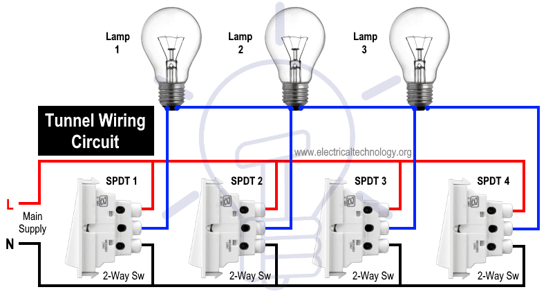
Types Of Electrical Diagrams from www.cmhsoftware.com Switches are shown as dotted rectangles. Wiring diagram since wiring connections and terminal markings are <br>in building wiring, a light switch is a switch, most commonly used to operate electric lights, permanently connected equipment, or electrical outlets. Here are ten simple electric circuits commonly found around the home. This connection is very simple connection and most used in electrical house wiring. The black wire will connect to your hot and the white wire connects to your neutral, green wire… Tunnel wiring circuit is used in open ended corridors and short tunnels like structures. Electrician circuit drawings and wiring diagrams youth explore trades skills 3 pictorial diagram:
Switch wiring shows the power source (power in) starts at the switch box.
Each protected by a 5 amp fuse or 6 amp trip in the consumer unit. The live is interrupted by the switch wiring and the circuit is carried on to the next junction box. To indicate static switching control, use the symbols shown in this. Always isolate any electrical circuit before working on the circuit. This is an updated version of the first arrangement. This connection can be done by one way switch, a light bulb socket, light bulb and electric wires. Basics 9 4.16 kv pump schematic : A node is simply a filled circle or dot. A lighting circuit can serve up to 12 x 100w bulbs. This topic explains 2 way light switch wiring diagram and how to wire 2 way electrical circuit with multiple light and outlet. Wiring diagrams use simplified symbols to represent switches, lights, outlets, etc. Wiring light switch is first step which learn by a electrician or electrical student. Here are ten simple electric circuits commonly found around the home.
Switch wiring shows the power source (power in) starts at the switch box. You need to make sure that you understand the. Fig 2 explanation of above picture. All the light wiring diagrams are available in the old and the new cable colours to avoid confusion. Basics 9 4.16 kv pump schematic :
Tunnel Wiring Circuit Diagram For Light Control Using Switches from www.electricaltechnology.org Each protected by a 5 amp fuse or 6 amp trip in the consumer unit. Electrical lines which include lighting circuits begin from the main distribution panel of the installation and each line contains three conductors: The live is interrupted by the switch wiring and the circuit is carried on to the next junction box. We have and extensive collection of common lighting arrangements with detailed lighting circuit diagrams, light wiring diagrams and a breakdown of all the components used in lighting circuits. All the light wiring diagrams are available in the old and the new cable colours to avoid confusion. Switch wiring shows the power source (power in) starts at the switch box. An electric circuit is a closed loop with a continuous flow of electric current from the power supply to the load. When you pull the light out of the box you will see that it has three wires.
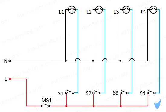
Another major defect of series lighting circuit is that as all lamps or bulbs are connected between line l and neutral n accordingly, if one of the light bulb gets faulty, the rest of the circuit will not work as the circuit will be open as shown in fig below.
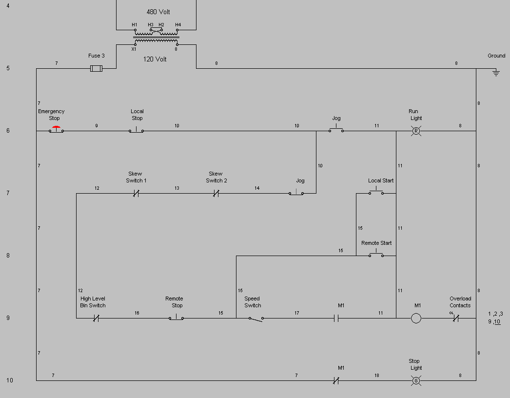
Static switching control is a method of switching electrical circuits without the use of contacts, primarily by solid state devices. Ceiling rose wiring diagrams are useful to help understand how modern lighting circuits are wired. Once tested and connected to the live supply, the lighting circuit will be operational. All the light wiring diagrams are available in the old and the new cable colours to avoid confusion. Tunnel wiring circuit is used in open ended corridors and short tunnels like structures. The black wire will connect to your hot and the white wire connects to your neutral, green wire… Wiring a switched outlet wiring diagram 3 way switch wiring diagram: A diagram that represents the elements of a system using abstract, graphic drawings or realistic pictures. Electrician circuit drawings and wiring diagrams youth explore trades skills 3 pictorial diagram: Duplex, gfci, 15, 20, 30, and 50amp receptacles. Black wire, white wire, and green wire. Wiring diagram of a one way lighting circuit using junction boxes (fig 1). This connection can be done by one way switch, a light bulb socket, light bulb and electric wires.
Wiring diagram of a one way lighting circuit using junction boxes (fig 1). Electrical lines which include lighting circuits begin from the main distribution panel of the installation and each line contains three conductors: Static switching control is a method of switching electrical circuits without the use of contacts, primarily by solid state devices. More about how to wire 220volt outlets. This electrical floor plan sample shows the lighting and switch layout.
Master Switch Wiring Diagram from mechatrofice.com Featuring wiring diagrams for single pole wall switches commonly used in the home. Wiring diagram of a one way lighting circuit using junction boxes (fig 1). The tunnel circuit control the lamps in four ways as follow. A wiring diagram is a simplified standard photographic depiction of an electrical circuit. Ceiling rose wiring diagrams are useful to help understand how modern lighting circuits are wired. Duplex, gfci, 15, 20, 30, and 50amp receptacles. <br>in building wiring, a light switch is a switch, most commonly used to operate electric lights, permanently connected equipment, or electrical outlets. Here is the wiring symbol legend, which is a detailed documentation of common symbols that are used in wiring diagrams, home wiring plans, and electrical wiring blueprints.
This electrical floor plan sample shows the lighting and switch layout.
In effect this is exactly the same wiring as the diagram on the top of the page, but with the utilisation of the flat twin&earth cable. Basics 9 4.16 kv pump schematic : Most arc welders require a dedicated electrical circuit and 220 volt outlet that is sized according to the specifications of the welder as described in further information. Now you know how to wire a basic lighting circuit with one light switched at one point. Electrical symbols and line diagrams chapter 3 material taken from chapter 3 of electric motor controls, g. Featuring wiring diagrams for single pole wall switches commonly used in the home. This is an updated version of the first arrangement. The above light switch wiring diagram depicts the power from the circuit breaker panel going to an electrical receptacle outlet and then continues to the next outlet and then to a single pole wall switch and then to another outlet. Tunnel wiring circuit is used in open ended corridors and short tunnels like structures. Each house should ideally have at least two lighting circuits; L and n indicate the supply. Lighting circuit diagrams these diagrams show various methods of one, two and multiple way switching. Electrical lines which include lighting circuits begin from the main distribution panel of the installation and each line contains three conductors: