Emergency Light Ballast Wiring Diagram / El 1248 Xx China Power Supply Battery Backup Battery Backup Led Emergency Light Manufacturer Supplier Fob Price Is Usd 37 0 61 0 Piece / A guide to emergency ballast for led and fluorescent lamps sanforce universal everline eld10unvl driver 10 watt 90 minute battery backup fixtures 120 277v input voltage 15 50vdc output class 2 at green electrical supply rapid start lampholder wiring 3 101 eld10unvlpl low profile 52vdc ufo ip65 170vdc eld20unvl highbays 20 4 70w 1000v dimmable light elp alternate… read more »
Emergency Light Ballast Wiring Diagram / El 1248 Xx China Power Supply Battery Backup Battery Backup Led Emergency Light Manufacturer Supplier Fob Price Is Usd 37 0 61 0 Piece / A guide to emergency ballast for led and fluorescent lamps sanforce universal everline eld10unvl driver 10 watt 90 minute battery backup fixtures 120 277v input voltage 15 50vdc output class 2 at green electrical supply rapid start lampholder wiring 3 101 eld10unvlpl low profile 52vdc ufo ip65 170vdc eld20unvl highbays 20 4 70w 1000v dimmable light elp alternate… read more ». Ll 2041 iota ballast wiring diagram i 320 instruction manual al 2158 light circuit on emergency lighting typical diagrams page 4 26 em a user 5 ob 4761 bodine 50b full version hd quality sitediagrams stefaisi it gc 1124 as well schematic 2 bpmdiagrams motorfit i32 reduced profile for linear fluorescent luminaires 32 or 24 of exit signs… read more » Emergency fluorescent light circuit diagram new wiring diagram for. Disconnect ac power from the fixture. Facturer is listed for ac ballasts that have unique wiring arrangements. This video is about emergency ballast replacement highlights
Diagrams for specific situations can be located within this pdf file by using the following methods: The diagrams are categorized primarily according to the number of. If a diagram cannot be found within this selection, consult customer service. Philips electronic ballast circuit diagram unique philips advance. Facturer is listed for ac ballasts that have unique wiring arrangements.

This product should only be installed by a qualified electrician !
Consult the factory for other wiring diagrams. It reveals the components of the circuit as simplified shapes, and the power and also signal connections between the tools. Remove the ballast channel cover and install the emergency ballast either in the ballast channel (see illustrations 1 & 2) or on top of the fixture* (see illustration 3). > after installation is complete, supply ac power to the emergency ballast and join the inverter connector. Facturer is listed for ac ballasts that have unique wiring arrangements. Cut back additional wiring on opposite side of ballast as the led tube lamp only requires power at one end. Instant start ballasts can only be wired in parallel according to the diagram on the ballast. And in compliance with local and national electrical codes. Remove the ballast from the Select the appropriate wiring diagram to connect the emergency ballast to the ac ballast and lamp. A wiring diagram is a streamlined traditional photographic representation of an electric circuit. Collection of fluorescent emergency ballast wiring diagram. It reveals the components of the circuit as streamlined shapes, and also the power and also signal connections between the devices.
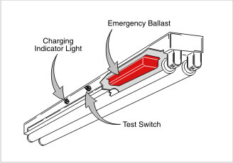
Emergency lighting units em inverter product description. Emergency ballast iiiustration 1 iiiustration 2 recessed troffer fixture strip fixture emergency ballast fixture ballast channel. Remove the ballast channel cover and install the emergency ballast either in the ballast channel (see illustrations 1&2) or on top of the fixture* (see illustration 3). Wiring diagrams for option 2. Fluorescent lampholder wiring electrical 101.
1) using the navigation window use the navigation window and select the emergency ballast for which the diagram is needed, then scroll through the list of applications to.
T8/t5 ballast wiring diagram available for reference online at eml direct. Remove the ballast channel cover and install the emergency ballast either in the ballast channel (see illustrations 1 & 2) or on top of the fixture* (see illustration 3). Philips electronic ballast circuit diagram unique philips advance. > select the appropriate wiring diagram on back to connect the emergency ballast to the ac ballast and lamp(s). If a diagram cannot be found within this selection, consult customer service. Connection instructions led tube light installation, ballast bypass cut the load and neutral wires from the ballast leaving a su˜cient amount of wire to connect back to the 110 vac power source. Refer to iiiustration 3 for switched and unswitched fixture wiring diagrams. 1) using the navigation window use the navigation window and select the emergency ballast for which the diagram is needed, then scroll through the list of applications to. Make sure all connections are in accordance with the national electrical code and any local regulations. Install in accordance with the national electrical code and local regulations. Remove the ballast channel cover and install the emergency ballast either in the ballast channel (see illustrations 1&2) or on top of the fixture* (see illustration 3). Sign ballasts smart wire parallel keystone technologies direct drive x2 s single end or double line voltage premier lighting ballast kteb 114 1 tp fc 120v electronic compact fluorescent for f14t5 f13t5 f21t5 cfq13w g24q cftr13w gx24q lamps 2 f8t5 f5t5 at www greenelectricalsupply com kt led12 5t8 48gc 850 d led 4ft t8 12 5w 5000k 1850… read more » The diagrams are categorized primarily according to the number of.
Input to the ballast must be connected ahead of the fixture switch. Emergency ballast and ac ballast must be fed from the same branch circuit. The diagrams are categorized primarily according to the number of. It reveals the components of the circuit as streamlined shapes, and also the power and also signal connections between the devices. > after installation is complete, supply ac power to the emergency ballast and join the inverter connector.

It reveals the components of the circuit as simplified shapes, and the power and also signal connections between the tools.
T8/t5 ballast wiring diagram available for reference online at eml direct. Remove the ballast from the It reveals the components of the circuit as simplified shapes, and the power and also signal connections between the tools. Here you will find a selection of wiring diagrams for converting existing t5 and t8 fluorescent fittings to emergency operation using the eck range of conversion kits. This product should only be installed by a qualified electrician ! A wiring diagram is a streamlined traditional photographic representation of an electric circuit. 1) using the navigation window use the navigation window and select the emergency ballast for which the diagram is needed, then scroll through the list of applications to. > select the appropriate wiring diagram on back to connect the emergency ballast to the ac ballast and lamp(s). Make sure all connections are in accordance with the national electrical code and any local regulations. Select the appropriate wiring diagram to connect the emergency ballast to the ac ballast and lamp. All diagrams are available in pdf format for viewing on almost any device. 3.wiring refer to the wiring diagrams on the back page for the appropriate wiring of lamp(s) and ballast. Refer to iiiustration 3 for switched and unswitched fixture wiring diagrams.