Home
› Basic Light Wiring Diagram - How To Wire Up Lights In Your Hotrod : Auto electrical wiring diagram, starting, charging system and all lighting system.
Basic Light Wiring Diagram - How To Wire Up Lights In Your Hotrod : Auto electrical wiring diagram, starting, charging system and all lighting system.
Basic Light Wiring Diagram - How To Wire Up Lights In Your Hotrod : Auto electrical wiring diagram, starting, charging system and all lighting system.. It shows the components of the circuit as simplified shapes, and the faculty and signal connections in the midst of the devices. A series circuit is a circuit in which. How to install a single tubelight with electromagnetic ballast. Wiring diagram a wiring diagram shows, as closely as possible, the actual location of all component a pilot light can be wired in parallel with the starter coil to indicate when the starter is energized wiring diagram. Is a visual representation of the components and cables.
800 x 600 px, source: As no starter is used in the case of electronic ballast application, the wiring diagram is slightly different. Basic electrical wiring installation diagrams. Fluorescent light wiring diagram | tube light circuit this is about how to wiring fluorescent light and how a fluorescent tube light works.wiring a service manual trucks group release wiring diagram fh chid a chid b chid w chid.basic wiring queenz kustomz. How to install a single tubelight with electromagnetic ballast.
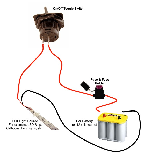
On Off Switch Led Rocker Switch Wiring Diagrams Oznium from lh5.googleusercontent.com As you can see all the installation is divided to 7 (can be more) different circuits to provide. Your home electrical wiring diagrams should reflect code requirements which help you enjoy lower energy bills when you implement energy efficiency into your. For example, a home builder will want to confirm the physical location of electrical outlets and light fixtures using a wiring diagram to avoid costly mistakes and building. 800 x 600 px, source: Wiring diagram a wiring diagram shows, as closely as possible, the actual location of all component a pilot light can be wired in parallel with the starter coil to indicate when the starter is energized wiring diagram. Out of these, the cookies that are categorized as necessary are stored on your browser as they are essential for the working of basic functionalities of the website. Fluorescent light wiring diagram | tube light circuit this is about how to wiring fluorescent light and how a fluorescent tube light works.wiring a service manual trucks group release wiring diagram fh chid a chid b chid w chid.basic wiring queenz kustomz. This light switch wiring diagram page will help you to master one of the most basic do it yourself projects around your house.
Hospital wiring circuit for light control using switches.
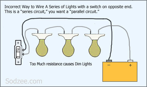
A series circuit is a circuit in which. Hospital wiring circuit for light control using switches. Click on any of the. House wiring diagrams including floor plans as part of electrical project can be found at this part of our website. Tube light circuit wiring diagram. As with all 3 way circuits the common on. As no starter is used in the case of electronic ballast application, the wiring diagram is slightly different. Here is the wiring symbol legend, which is a detailed documentation of usually, circuits with more than two components have two basic types of connections: Please note that im only showing the black hot and white neutral conductors in this drawing and not the ground wire. Whether you have power coming in through the switch or from the lights, these switch wiring diagrams will show you the light. Wiring diagram of single tube light installation with electronic ballast. Electronic ballast has six ports, two ports out of six. In the illustrations of the logo!
Wiring diagram of single tube light installation with electronic ballast. As with all 3 way circuits the common on. 1.0mm tps or 1.5mm tpsi'll be uploading a few 'basic' videos for beginners while filming more advanced videos.warning: Electronic ballast has six ports, two ports out of six. As no starter is used in the case of electronic ballast application, the wiring diagram is slightly different.
Simple Home Electrical Wiring Diagrams Sodzee Com from sodzee.files.wordpress.com As you can see all the installation is divided to 7 (can be more) different circuits to provide. House wiring diagrams including floor plans as part of electrical project can be found at this part of our website. Residential electrical wiring layouts and explanation of the process of home electrical wiring. A wiring diagram is a simple visual representation of the physical connections and physical layout of an electrical system or circuit. Class 8502 type pe contactor w/ class 9065 type te overload relay. Basic light wiring diagrams book download good option after you had successfully register to our book vendor. Auto car wiring diagram basic circuit for installation relay connection spot light fog lamp insta. Do not attempt to diy.
A wiring diagram is a simple visual representation of the physical connections and physical layout of an electrical system or circuit.
Here is the wiring symbol legend, which is a detailed documentation of usually, circuits with more than two components have two basic types of connections: Auto electrical basic wiring diagram and connection, starting and charging system connection. January 4, 2019january 3, 2019. Wiring diagram a wiring diagram shows, as closely as possible, the actual location of all component a pilot light can be wired in parallel with the starter coil to indicate when the starter is energized wiring diagram. Wiring diagram of single tube light installation with electronic ballast. Wiring a basic light switch, with power coming into the switch and then out to the light is illustrated in this diagram. A wiring diagram is a simple visual representation of the physical connections and physical layout of an electrical system or circuit. Below are several of the top illustrations we obtain from different resources, we hope these photos will work to you, as well as with any luck extremely relevant to what you desire regarding the. Please note that im only showing the black hot and white neutral conductors in this drawing and not the ground wire. Tube light circuit wiring diagram. 800 x 600 px, source: As with all 3 way circuits the common on. Basic electrical wiring installation diagrams.
As you can see all the installation is divided to 7 (can be more) different circuits to provide. Your home electrical wiring diagrams should reflect code requirements which help you enjoy lower energy bills when you implement energy efficiency into your. Hostel wiring circuit diagram and working. Basic light wiring diagrams book download good option after you had successfully register to our book vendor. Electronic ballast has six ports, two ports out of six.
Schematics And Wiring Diagrams Circuit 1 from www.industrial-electronics.com Auto electrical wiring diagram, starting, charging system and all lighting system. This topic explains 2 way light switch wiring diagram and how to wire 2 way electrical circuit with multiple light and outlet. Basic electrical wiring installation diagrams. Auto electrical basic wiring diagram and connection, starting and charging system connection. This application example describes how to implement basic light circuits using logo! Class 8502 type pe contactor w/ class 9065 type te overload relay. For example, a home builder will want to confirm the physical location of electrical outlets and light fixtures using a wiring diagram to avoid costly mistakes and building. Wiring diagram of single tube light installation with electronic ballast.
A wiring diagram is a simple visual representation of the physical connections and physical layout of an electrical system or circuit.
Learning those pictures will help you better understand the basics of home lights wiring diagram. Simple electrical wiring diagrams basic light switch diagram in a, size: Hostel wiring circuit diagram and working. Tube light circuit wiring diagram. Below are several of the top illustrations we obtain from different resources, we hope these photos will work to you, as well as with any luck extremely relevant to what you desire regarding the. Wiring diagrams use simplified symbols to represent switches, lights, outlets, etc. Your home electrical wiring diagrams should reflect code requirements which help you enjoy lower energy bills when you implement energy efficiency into your. Watch and learn how to replace a light switch. Basic electrical wiring installation diagrams. Out of these, the cookies that are categorized as necessary are stored on your browser as they are essential for the working of basic functionalities of the website. A wiring diagram is a simple visual representation of the physical connections and physical layout of an electrical system or circuit. When there are lots of distinct kinds of diagrams which can be created. Auto electrical basic wiring diagram and connection, starting and charging system connection.