Home
› Trailer Hook Up Diagram / 30 best images about Expedition Trailer info on Pinterest | Portal, Adventure trailers and ... - February 1, 2020 april 12, 2020 · wiring diagram by anna r.
Trailer Hook Up Diagram / 30 best images about Expedition Trailer info on Pinterest | Portal, Adventure trailers and ... - February 1, 2020 april 12, 2020 · wiring diagram by anna r.
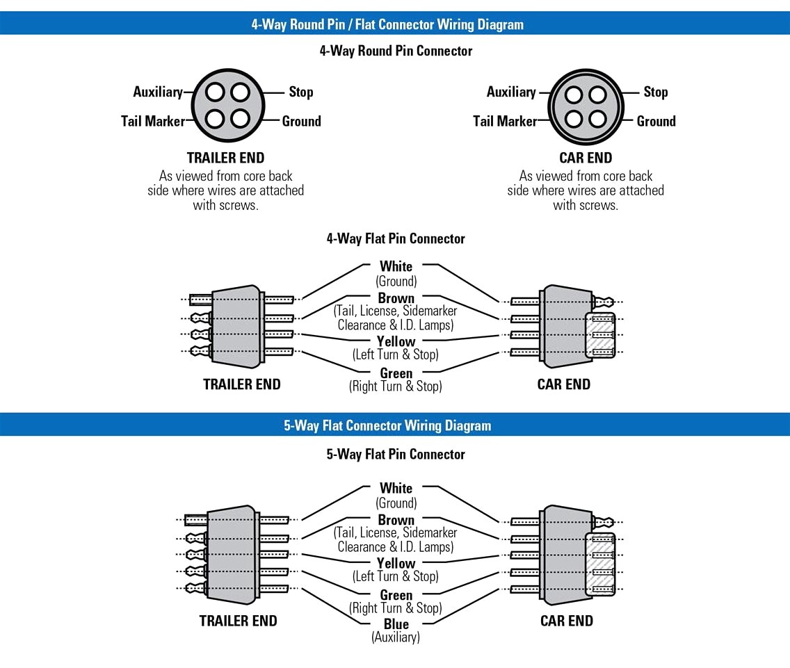
Trailer Hook Up Diagram / 30 best images about Expedition Trailer info on Pinterest | Portal, Adventure trailers and ... - February 1, 2020 april 12, 2020 · wiring diagram by anna r.. Load a boat by yourself in seconds with the drotto latch. 7 way plug wiring diagram standard wiring* post purpose wire color tm park light green (+) battery feed black rt right turn/brake light brown lt left turn/brake light red s trailer electric brakes blue gd ground white a accessory yellow this is the most common (standard) wiring scheme for rv plugs and the one used by major auto manufacturers today. It doesn't connect to any lights. Right turn signal / stop light (green), left turn signal / stop light (yellow), taillight / license / side marker (brown) and a ground (white). A trailer hitch is the primary connector between a tow vehicle and trailer.
The image above shows a single axle trailer, and the next image shows wiring for tandem axles. Check to make sure there is a signal going into and coming out of the converter or modulite box without the trailer hooked up. Trailers are required to have at least running lights, turn signals and brake lights. Most of us aren't electricians, but that doesn't mean wiring a trailer or replacing corroded wiring is beyond us. If not, the arrangement will not function as it ought to be.
Wiring Diagram For A Trailer Hook Up from lh6.googleusercontent.com A ball mount, however, is simply an accessory. It gets complicated when you have trailers with more cables, and in this case, you need an adapter to make the connections. It will help to have an understanding of trailer light systems and we recommend reviewing trailer wiring diagrams before starting this project. The first step in wiring your trailer cables is to ground the white cable first. Typical trailer wiring diagram and schematic these 2 wire diagrams fit the needs of most trailers. If your vehicle is not equipped with a working trailer wiring harness, there are a number of different solutions to provide the perfect fit for. A wiring diagram is a simplified standard photographic depiction of an electric circuit. Trailer wiring diagram to connect the electric system of your trailer to the vehicle, you will be using special connector.
If not, the arrangement will not function as it ought to be.
And we offer so much more than that! Trailer wiring diagram to connect the electric system of your trailer to the vehicle, you will be using special connector. A wiring diagram is a simplified standard photographic depiction of an electric circuit. To hook up a trailer, move the trailer to an open stretch of driveway if you can, and position it so you can approach it in a straight line with your vehicle. If not, the arrangement will not function as it ought to be. It gets complicated when you have trailers with more cables, and in this case, you need an adapter to make the connections. Below is the generic schematic of how the wiring goes. Trailer side car side wiring plug diagram. When you think trailer hitch, you might picture what is actually referred to as a ball mount. It is the structural component that bolts onto the vehicle and provides a coupling point to hook up a trailer. The white wire coming from your new harness is your ground wire that needs to be fastened to the trailer up front to get your ground. The only part of the wiring harness that will typically go bad is. 4 way tow vehicle side.
Trailer side car side wiring plug diagram. This is a short video series of the steps that i have taken to refurbish and old utility trailer that was designed and built by my father. Drotto is the best boat loading latch on the market. As the name implies, they use four wires to carry out the vital lighting functions. This trailer hook up wiring diagram model is far more appropriate for sophisticated trailers and rvs.
Trailer Wiring Diagrams | North Texas Trailers | Fort Worth from www.northtexastrailers.com Typical trailer wiring diagram and schematic these 2 wire diagrams fit the needs of most trailers. The four wires control the turn signals, brake lights and taillights or running lights. Below is the generic schematic of how the wiring goes. Where do they hook up, or which color to which color? February 1, 2020 april 12, 2020 · wiring diagram by anna r. Trailer side car side wiring plug diagram. The only part of the wiring harness that will typically go bad is. Above we have describes the main types of trailer wiring diagrams.
Drotto boat latch on boat2trailer.
Check to make sure there is a signal going into and coming out of the converter or modulite box without the trailer hooked up. It doesn't connect to any lights. A simple closed system while it's never a good idea to dive into a wiring project blind, trailer wiring is actually very simple to work on and troubleshoot. The white wire coming from your new harness is your ground wire that needs to be fastened to the trailer up front to get your ground. It is the structural component that bolts onto the vehicle and provides a coupling point to hook up a trailer. This is a short video series of the steps that i have taken to refurbish and old utility trailer that was designed and built by my father. Let's see what types of connectors the trailer light wiring industry uses today. This guide will be discussing trailer breakaway box wiring diagram.what are the benefits of knowing such knowledge? Above we have describes the main types of trailer wiring diagrams. The first step in wiring your trailer cables is to ground the white cable first. Drotto is the best boat loading latch on the market. This diagram shows the colors of a basic trailer wiring setup as well as what each wire is supposed to be connected to. A ball mount, however, is simply an accessory.
Trailer wiring diagrams 4 way systems 4 way flat molded connectors allow basic hookup for three lighting functions; It shows the components of the circuit as simplified shapes, and the capability and signal associates amongst the devices. Above we have describes the main types of trailer wiring diagrams. It is the structural component that bolts onto the vehicle and provides a coupling point to hook up a trailer. It gets complicated when you have trailers with more cables, and in this case, you need an adapter to make the connections.
HOOKING UP: a how to guide for people with trailers from cdn.slidesharecdn.com Stop into our harrisburg, pa dealership today or call to learn more! This guide will be discussing trailer breakaway box wiring diagram.what are the benefits of knowing such knowledge? The image above shows a single axle trailer, and the next image shows wiring for tandem axles. We're happy to help guide our customers to the right trailer or snow plow for them. Trailer side car side wiring plug diagram. It shows the parts of the circuit as simplified shapes, as well as the power as well as signal connections in between the tools. Trailer wiring diagrams 4 way systems 4 way flat molded connectors allow basic hookup for three lighting functions; To hook up a trailer, move the trailer to an open stretch of driveway if you can, and position it so you can approach it in a straight line with your vehicle.
White pin to your ground.
Where do they hook up, or which color to which color? Variety of dodge trailer wiring diagram 7 pin. The first step in wiring your trailer cables is to ground the white cable first. Check to make sure there is a signal going into and coming out of the converter or modulite box without the trailer hooked up. Most of us aren't electricians, but that doesn't mean wiring a trailer or replacing corroded wiring is beyond us. Drive your vehicle forward so it's directly in front of the trailer, and then slowly reverse as directly in line with the trailer as you can. Check to make sure there is a signal going into and coming. A trailer hitch is the primary connector between a tow vehicle and trailer. Typical trailer wiring diagram and schematic these 2 wire diagrams fit the needs of most trailers. 4 way tow vehicle side. Right turn signal / stop light (green), left turn signal / stop light (yellow), taillight / license / side marker (brown) and a ground (white). It gets complicated when you have trailers with more cables, and in this case, you need an adapter to make the connections. 7 way plug wiring diagram standard wiring* post purpose wire color tm park light green (+) battery feed black rt right turn/brake light brown lt left turn/brake light red s trailer electric brakes blue gd ground white a accessory yellow this is the most common (standard) wiring scheme for rv plugs and the one used by major auto manufacturers today.