Home
› Control Diagram Symbols - Control Systems Block Diagrams Tutorialspoint - The orientation of a symbol on a drawing, including a mirror image presentation, does not alter the meaning of the symbol.
Control Diagram Symbols - Control Systems Block Diagrams Tutorialspoint - The orientation of a symbol on a drawing, including a mirror image presentation, does not alter the meaning of the symbol.
Control Diagram Symbols - Control Systems Block Diagrams Tutorialspoint - The orientation of a symbol on a drawing, including a mirror image presentation, does not alter the meaning of the symbol.. Basics 10 480 v pump schematic : To show equipment arrangement any number of specific symbols, hence functions, that are Schematic diagrams with graphical symbols are used to show the electrical connections and functions of a specific circuit. Schematic diagrams show components in their electrical sequence without regard for physical location.schematic diagrams are used to troubleshoot and install control circuits. The message in the name determines the type of component, every component's name on an electrical schematic should be unique.
The orientation of a symbol on a drawing, including a mirror image presentation, does not alter the meaning of the symbol. Control diagram symbols plcs net interactive q a from www.plctalk.net what should be consulted for the specific symbols used in a set of logic prints? When designing software, we need to understand how the control of the program flows. Directional air control valves are the building blocks of pneumatic control. Use rectangles to capture process steps like basic tasks or actions in your process.
Jic Standard Symbols For Electrical Ladder Diagrams Womack Machine Supply Company from www.womackmachine.com A step in the flowcharting process. Hydraulic and pneumatic picture symbols for fluid power schematics, define their function in engineering drawings, diagrams, or plans. 21 posts related to german wiring diagram symbols. Piping and instrumentation diagrams (p&ids) use specific symbols to show the connectivity of equipment, sensors, and valves in a control system. Most of the industrial standard circuit items can be changed in the appearance, style and color according to the requirement. The pressure is generally sup plied by someone's finger pressing on the button. Here is a picture gallery about control wiring diagram symbols complete with the description of the image, please find the image you need. Basics 14 aov schematic (with block included)
This tool takes a function block diagram (fbd) as an input model and integrates the uppaal 23 model checker to perform symbolic reachability analysis on fbd models for test case generation.
The following are the circuit symbols commonly used in motor related schematic diagrams. Symbols for hvac system components refer to ashrae fundamentals handbook 2005 chp. Basics 10 480 v pump schematic : Schematic diagrams show components in their electrical sequence without regard for physical location.schematic diagrams are used to troubleshoot and install control circuits. Electrical symbols and line diagrams chapter 3 material taken from chapter 3 of electric motor controls, g. 4.2.4 combination of symbols each specific function represented by a symbol is drawn in a separate enclosure. Basics 13 valve limit switch legend : One of the most used symbols in control schematics is the push button. Electrical symbols electrical projects electrical installation electrical wiring electrical engineering ac wiring chemical engineering engineering projects arduino projects. The width of a line does not affect the meaning of the symbol. Pneumatic circuit symbols representing these valves provide detailed information about the valve they represent. The above block diagram consists of two blocks having transfer functions g (s) and h (s). Basics 9 4.16 kv pump schematic :
Schematic symbols and circuit design help. Building wiring diagram with symbols. Symbol for key diagram, m.v. Diagram with connecting lines or reference notes used to indicate connections to other parts of the diagram or system. Basics 14 aov schematic (with block included)
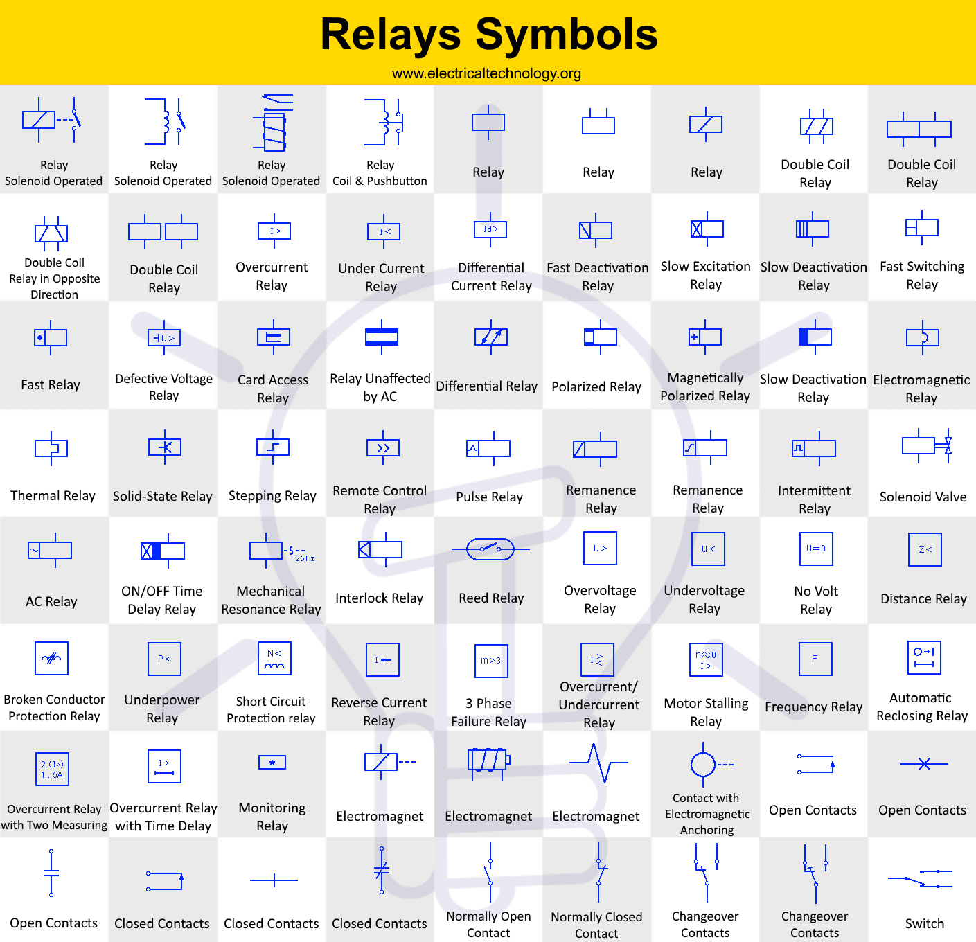
Relays Symbols Coil Solenoid Electromagnet Contacts Symbols from www.electricaltechnology.org The following are the circuit symbols commonly used in motor related schematic diagrams. Learn how to explain each componen. Electrical symbols and line diagrams chapter 3 material taken from chapter 3 of electric motor controls, g. Basic elements of block diagram. Here is a brief breakdown of how to read a symbol. Pneumatic circuit symbols representing these valves provide detailed information about the valve they represent. Hydraulic and pneumatic picture symbols for fluid power schematics, define their function in engineering drawings, diagrams, or plans. The orientation of a symbol on a drawing, including a mirror image presentation, does not alter the meaning of the symbol.
Symbols for hvac system components refer to ashrae fundamentals handbook 2005 chp.
Although control symbols vary throughout the world, the symbols used in this course are common in the united states and many other countries. The following are the circuit symbols commonly used in motor related schematic diagrams. Navy's fluid power training course. These symbols can represent actuators, sensors, and controllers and may be apparent in most, if not all, system diagrams. Most of the industrial standard circuit items can be changed in the appearance, style and color according to the requirement. This lesson will explain the control flow diagram. Basics 8 aov elementary & block diagram : Pneumatic circuit symbols representing these valves provide detailed information about the valve they represent. Piping and instrumentation diagrams (p&ids) use specific symbols to show the connectivity of equipment, sensors, and valves in a control system. The following tables describe the device and show the symbol by area of usage. Basics 14 aov schematic (with block included) Basics 9 4.16 kv pump schematic : Circuit symbols are used in circuit schematic diagrams which show how a circuit is connected together electrically.
Circuit symbols are used in circuit schematic diagrams which show how a circuit is connected together electrically. Based on your observations of these two diagrams, explain how electromechanical relays are represented differently between ladder and schematic diagrams. Push buttons can be shown as normally open or normally closed (fig. Electrical wiring diagram symbols pdf. Schematics are generally easier to read and understand than wiring diagrams.
Via Giphy Electrical Circuit Diagram Electrical Symbols Wiring Diagram from i.pinimg.com Most of the industrial standard circuit items can be changed in the appearance, style and color according to the requirement. These symbols can represent actuators, sensors, and controllers and may be apparent in most, if not all, system diagrams. The orientation of a symbol on a drawing, including a mirror image presentation, does not alter the meaning of the symbol. Use rectangles to capture process steps like basic tasks or actions in your process. Directional air control valves are the building blocks of pneumatic control. Basic elements of block diagram. When designing software, we need to understand how the control of the program flows. Basics 8 aov elementary & block diagram :
One of the more common approaches is to use control logic diagrams which use common symbols to represent control components.
This tool takes a function block diagram (fbd) as an input model and integrates the uppaal 23 model checker to perform symbolic reachability analysis on fbd models for test case generation. Here is a brief breakdown of how to read a symbol. Push buttons can be shown as normally open or normally closed (fig. Electrical control panels are available in all shapes and sizes to suit the particular requirements of the situation. The purpose of this document is to provide a simple cross reference of common schematic/wiring diagram symbols used throughout various parts of the world. Learn how to explain each componen. The standard circuit component symbols and circuit symbols are important for circuit schematic diagrams. The following tables describe the device and show the symbol by area of usage. The message in the name determines the type of component, every component's name on an electrical schematic should be unique. It represents any step in the process you're diagramming and is the workhorse of the flowchart diagram. Other symbols may be used on industrial control diagrams provided a suitable explanation is given to their meaning. Basic elements of block diagram. 37, abbreviations and symbols refer to other local standards or guidelines usually specified in the contract drawings & documents generic control diagrams using generic symbols to describe and define the requirements of the control system