Mac Valve Wiring Diagram
24712201 electric / air control valve 1945 normally closed 24712202 electric / air control valve 2345 normally open 24712212 12v parker inline pilot valve 24000604 breather www.mactrailer.com mac trailer mfg. • pressure seal between valve and base :
30 Mac Valve Wiring Diagram Wiring Database 2020

It is important to note that a proper safety barrier needs to be used in conjunction with the solenoid valve.

Mac valve wiring diagram. Grounded filter separator 72″ x 30″ x 6″. Mac valve wiring diagram from www.therangerstation.com to properly read a electrical wiring diagram, one provides to learn how typically the components inside the system operate. Wiring diagram for lighting contactor inspirationa wiring diagram.
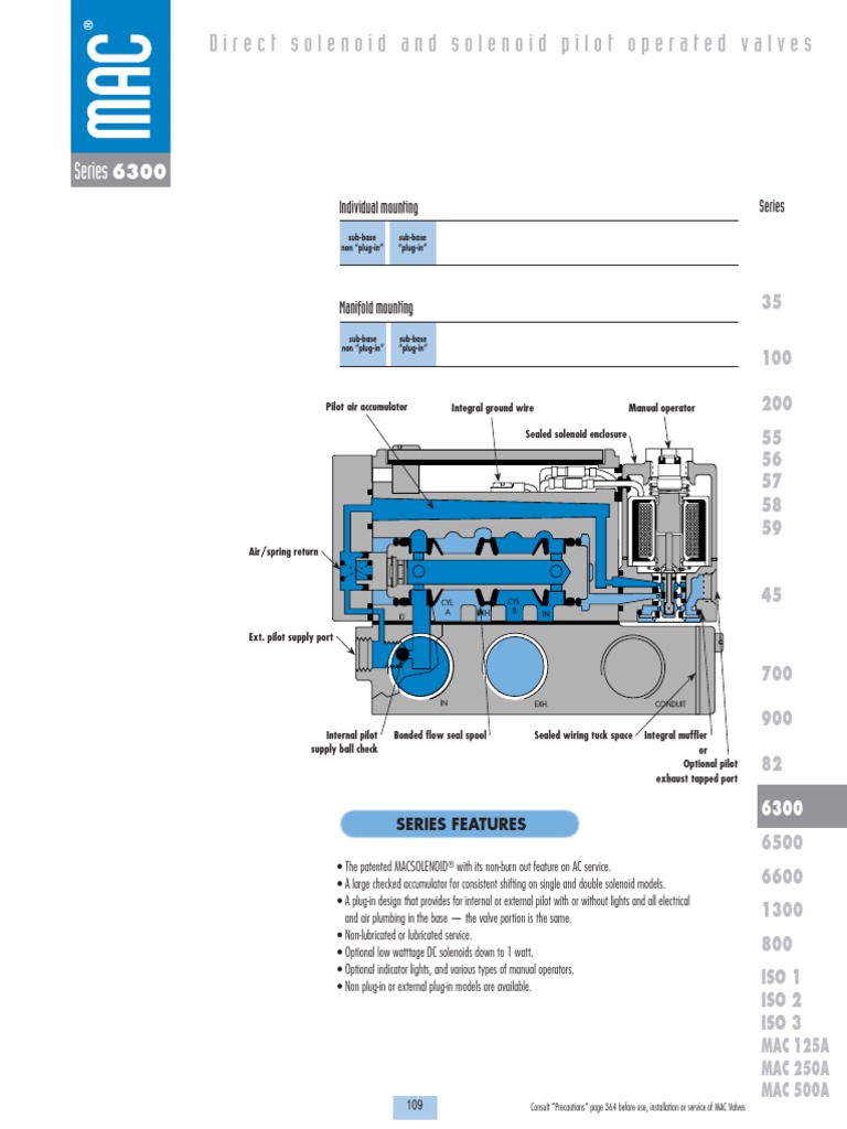
A b f71 15a center pin hot a b f60 30a hvac fan a b f61 5a lvd sens/ vendor ttu a b f76 30a 3968162 a f05 30a lecm4 b f06 20a rh sleeper pwr ports/ console b. Dimensions technical data dimensions shown are metric (mm) consult "precautions" page 364 before use, installation or service of mac valves 100% 18 100%. 4″ dual vacuum producer filter separator equipment.
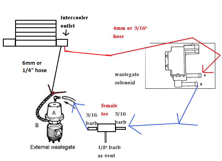
It is not recommended to mount the valve in a direct, extreme heat source so, if you can, mount it off to the side of your engine bay keeping maximum valve temps at or under 122*f. We found mac valve wiring diagram and we suppose this is one of many awesome content for reference. • maximum allowable coil amperage is 250 milliamps.
Itulah sebabnya website ini banyak diminati para. • left or right end connector adapters available. Mac valve wiring diagram furthermore ls1 pcm wiring diagram further air pressor wall together with kohler ch18 parts diagram in addition hondata s300 wiring diagram.
Mac control valve manifold pneumatic air valve bank 150 psi 6523b 6513b. Search in mac valves catalogs and technical brochures on directindustry and find the information you need in 1 click. Since 1948, mac valves, inc.
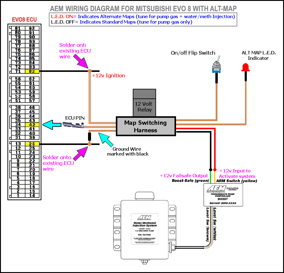
Wiring information maconnect information™ precautions page 31 32 34 mac valves commonly ordered products catalog table of contents. For example , when a module is powered up and it also sends out the signal of half the voltage and the technician will not know this, he'd think he offers a problem, as he would expect a 12v signal. One wire connects to a 12 volt source, the other to the megasquirt, the valve wiring is not polarized so it does not matter which wire you run to 12v+ and which to switched ground at the ems.
Grounded filter separator 84″ x 38″ x 6″. Hepa filter 4″ & enclosure. Grounded filter separator 72″ x 30″ x 6″.
4 wire schematic for latching. Diagram mac control valve wiring full version hd quality old honeywell v8043 need help zone valves doityourself com community forums adding to weil mcclain he boiler heating the wall locating c for ecobee install with v8043e1012 connect line voltage hot water piping 1 faqs how or wire a taco 24v sandy ed u can you terry love plumbing read more. • mounting screw valve to base (x4) :
The power to the solenoid comes from the 12v power supply circuit. Power distribution frc 1/2 wiring diagram: Manual reset valves figures 4a 4b manual reset valves must be manually latched into position and will return to their original position only when the solenoid has been energized or de energized depending on construction engineering information solenoid.
The mac valve bullet valve® pump is designed to handle the toughest and most critical dosing applications. Setiap artikel dibahas secara tuntas dengan penyajian bahasa yang gampang dipahami bagi orang awam sekalipun. The bullet valve® pump is perfect applications wit.
• standard ac and dc voltage options available up to 240 volts. Grounded filter separator 84″ x 38″ x 6″. Hepa filter 4″ & enclosure.
Mac 1175 wiring diagram installation instructions com delay on break g c r no nc delay on make white black equipment ground 120v 24v gas valve white white white red red timer l yellow yellow 24v leads to thermostat yellow limit switch red terminal board black black white black black air circulator receptacle transformer mac 1175. Has worked to establish and maintain global technological leadership in the design and manufacture of pneumatic and fluid valves, proportional valves, flow control, and regular technology.
30 Mac Valve Wiring Diagram Wiring Database 2020
34 Mac Valve Wiring Diagram Wiring Diagram Database


Mac Valve Wiring Diagram Wiring Diagram
30 Mac Valve Wiring Diagram Wiring Diagram List

30 Mac Valve Wiring Diagram Wiring Database 2020
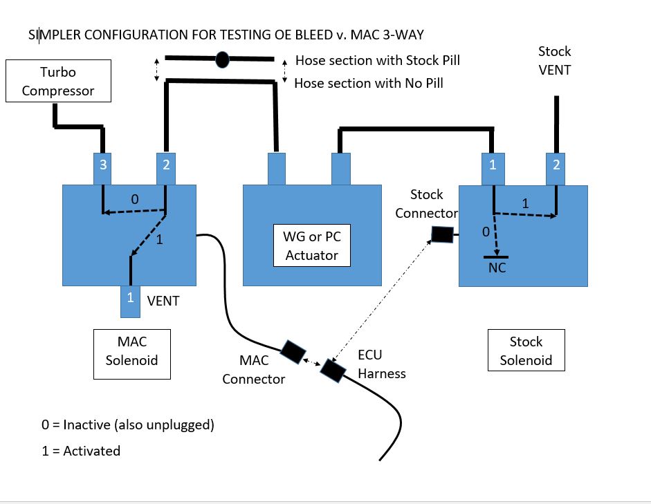
Testing MAC vs. OE solenoid valves and other boost control

3 Way Mac Valve Wiring Diagram Wiring Diagram
Mac Valve Wiring Diagram General Wiring Diagram

30 Mac Valve Wiring Diagram Wiring Diagram List
Network Cables Diagram — UNTPIKAPPS


Mac Valve Wiring Diagram Wiring Diagram
30 Mac Valve Wiring Diagram Wiring Database 2020
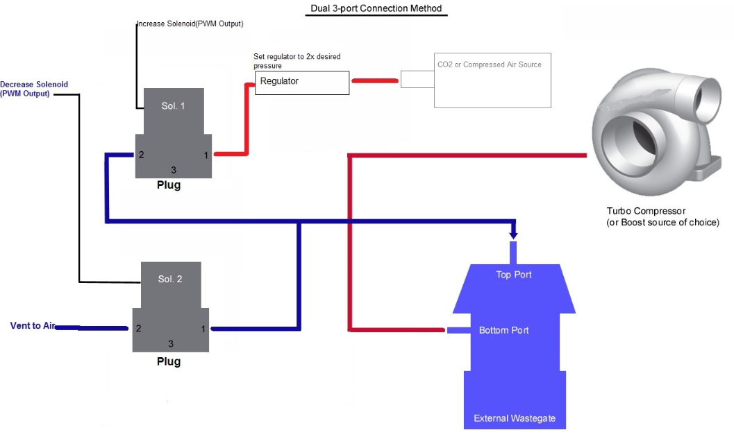
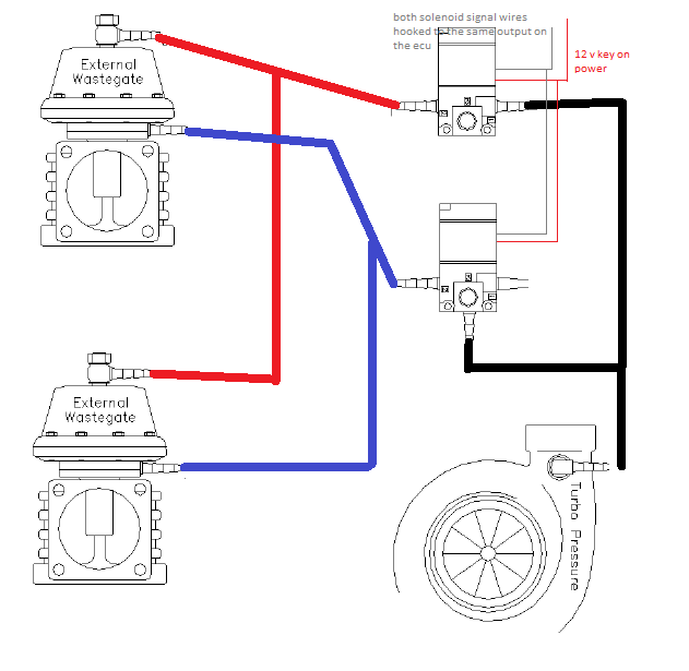
How do i plumb and wire in dual MAC valves for boost
Mac Valve (Holley CO2 Boost Control Solenoid) 90 degree
Mac Valve Wiring Diagram Derslatnaback


Mac Valve Electrical Wiring Wiring Diagram
Millivolt Gas Valve Wiring Diagram Drivenheisenberg

Mac Valve Wiring Diagram Derslatnaback
Mac Valve Wiring Diagram Derslatnaback
