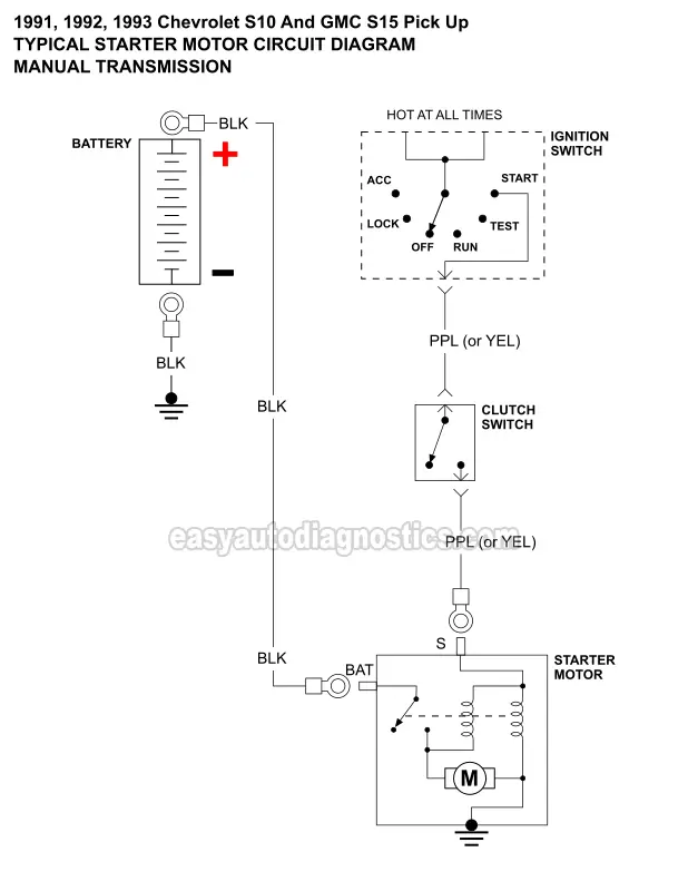
Switch Board Circuit Diagram
The touch sensor can be constructed using a small piece of a printed circuit board ( two small tracks with a 2 mm distance between each other ). For example, the following pictorial diagram shows a two section switchboard.

Furnas Drum Switch Wiring Diagram Wiring Diagrams
Electrical switch board wiring diagram switch box wiring or switchboard wiring is a common wiring arrangement used in most house electrical wirings or switchboards.

Switch board circuit diagram. Here, we have already build a 5v dc relay module for testing electronics circuits. Usb 5v to 1.5v /3v dc adapter. The hot and neutral terminals on each fixture are spliced with a pigtail to the circuit wires which then continue on to the next light.
A very simple electronic touch switch can be constructed using this circuit diagram. Good phone doctors must also learn how to identify spare parts, android phone parts, and how each parts of android phone work on a. How to wire up a switchboard in the below wiring diagram, the phase line is connected.
It gets back to its original state when an external clock pulse is given to a monostable oscillator. I'm also interested in learning about this kind of circuit. Distribution board is also known as "fuse board", "panel board.
Fig 4 shows that how to wire a four poles, three phase manual changeover switch to the main distribution board. The given circuit is a basic switchboard wiring for a light switch (one lamp controlled by one switch) and 3 pin plug socket with control switch. Clap switch circuit diagram clap switch circuit diagram the entire function of the clap switch is based on cd 4017 ic and ne 555 ic.
Ⅳ principle of input circuit and common circuit 4.1 principle of ac input rectification and filtering circuit. We also include mobile phone circuit board parts, mobile pcb diagram, mobile pcb board diagram and smart phone pcb repairing updated information 2019 on mobile pcb board components pdf here in this blog post. This electronic touch switch is based on two transistors an can activate a relay , when the touch sensor is pressed.
Circuit drawing (diagram):a simplified conventional graphical representation of an electrical circuit. The given circuit is a basic switchboard wiring for a light switch (one lamp controlled by one switch) and 3 pin plug socket with control switch. Block diagram of switching power supply circuit.
Many ideas of 12v and 5v dual power supply circuit diagram at 3a max; The photocell used in the circuit is named as dark sensing circuit otherwise transistor switched circuit. Once we tune the sensitivity (temperature) level this circuit becomes automatic temperature controlled switch, this circuit requires few affordable components and can be prototype with the dot board.
When there is a lightning strike, high voltage is generated through the power grid. Pin1 of both the switches are connected with the phase or live wire and pin2 of both the switches are connected with the one end of the lamp. Two kinds of pins are used (85 & 86) to regulate the coil, and 2 pins are used (30 & 87) to switch power on a single board/circuit.
Ir remote control switch circuit diagram in above ir remote control light switch, output of tsop1738 oscillates at the rate of 38khz, which is applied to clock pulse of 4017. You should probably use a dc to dc converter as a switching mode power supply circuit. Temperature sensor lm35 is used in this circuit to detect temperature and relay switch turns on and off the target electrical load or appliances.
Ic 555 is a timer ic it is similar to an oscillator like monostable, which has only one stable state. By using hammer and snail on the wood board. This diagram illustrates wiring for one switch to control 2 or more lights.
The other end of the lamp is connected with the neutral line of ac power supply. The three phase utility power as (l1, l2, l3 & n) are directly connected to the upper side. This is the same connection as we discussed above for single phase wiring expect that there are three phase wires instead of line and neutral.
Schematic of input filter, rectifier circuit. Normally open and normally closed. Touch based switch board using ttp223 is ready for testing.
After connecting all components as per circuit diagram it's time for testing. So we have connected a 1uf capacitor across the output of the tsop so that this 38khz pulse train is counted as one clock pulse to the ic 4017. Distribution board is a safe system designed for house or building that included protective devices, isolator switches, circuit breaker and fuses to connect safely the cables and wires to the sub circuits and final sub circuits including their associated live (phase) neutral and earth conductors.
Here the switch is connected to digital pin 4 (d4) and led is connected to digital pin 8 (d8) of arduino uno. Photocell circuit diagram working types and its.
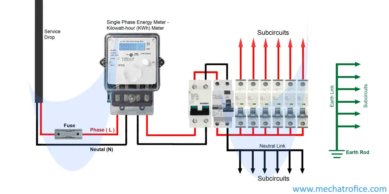
electric board circuit diagram Wiring Diagram

3 phase wiring installation in house 3 phase distribution

Single Pole Thermostat Wiring Diagram at Wiring Diagram

diagram of how to wire a light switch Irish Connections
electric board circuit diagram Wiring Diagram
10+ Electric Board Wiring Diagram Robhosking Diagram

Wiring Diagram of the Distribution Board Mechanical

electric board circuit diagram Wiring Diagram
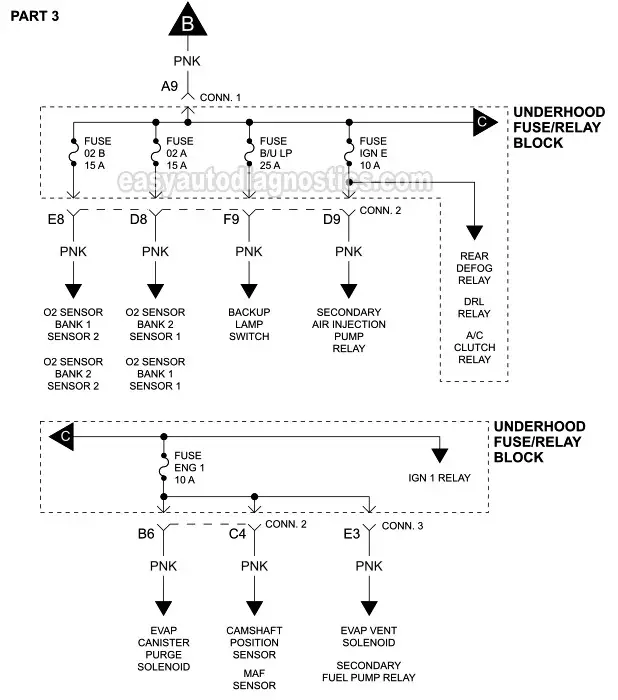
2003 silverado ignition switch wiring diagram Irish

Electronics project remote control switch circuit diagram

Download Electrical Panel Board Wiring Diagram Wiring Sample
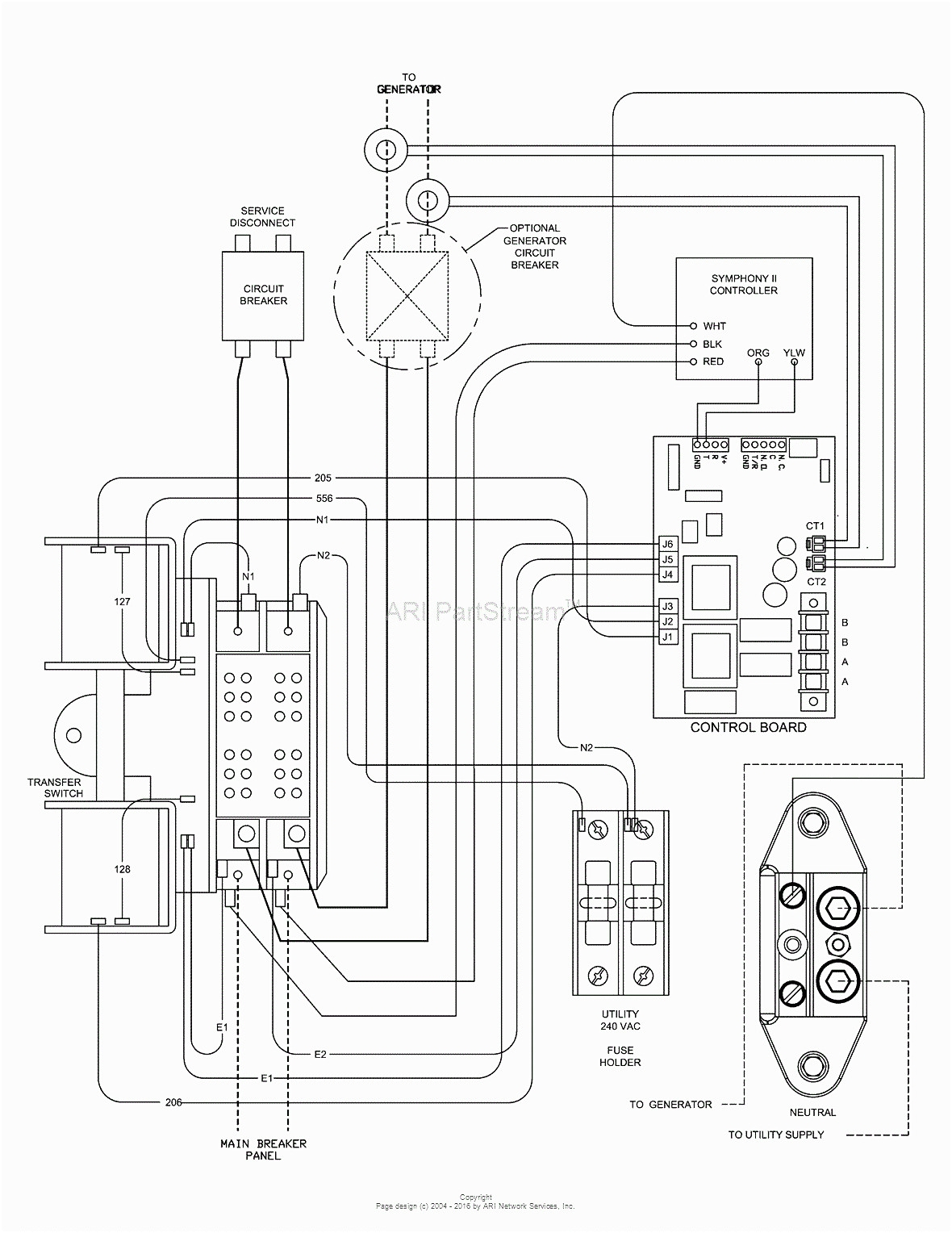
Auto Transfer Switch Wiring Diagram autocardesign

Download Electrical Panel Board Wiring Diagram Wiring Sample

PowerSchematicWiringDiagram RAUR.US
Prototyping 7 Wiring diagrams and Circuit schematic

Single Pole Thermostat Wiring Diagram at Wiring Diagram
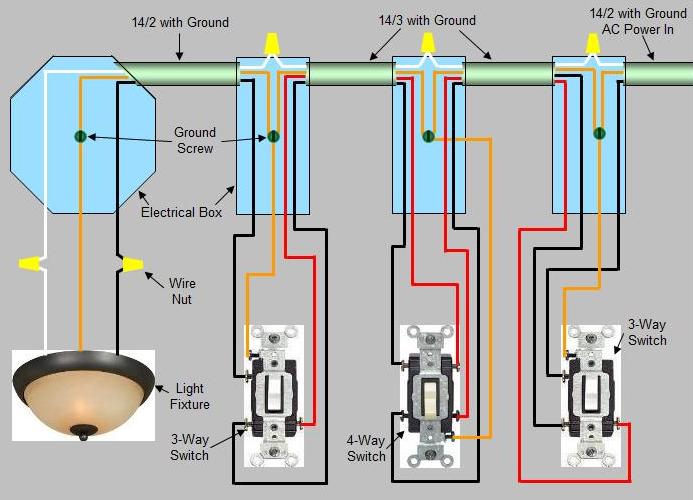
wiring multiple 3 way switches in one box DHNX Wiring
