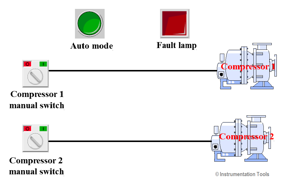
Air Compressor Control Circuit Diagram : Air Suspension System / Air compressor system schematic diagram.. An air compressor generates power in the form of air pressure, and for an air compressor to work efficiently it requires a certain unit. There are several control methods available for air compressors, which may greatly affect the overall operating efficiency of the compressor. A wiring diagram is a streamlined conventional pictorial depiction of an electric circuit. Ou can select to run just compressor a or compressor by. Control and shutdown schemes, diagrams of plumbing systems, heating schemes, schematics of waste water disposal systems, safety and regulatory requirements, diagrams of ventilation systems, mechanical diagrams, industrial diagrams, basic start up and operational information.
As a result, perhaps the central pneumatic air compressor owner/user family, which is a huge one, can offer advice as some of them will, undoubtedly, already dealt with the same problem you are experiencing with your hf central pneumatic air compressor. Nema and iec markings and schematic diagrams.4 control and power connection table 4. Regulations for noise emissions applicable to portable air compressors. It shows the parts of the circuit as simplified shapes, as well as the power as well as signal connections between the devices. Measured 120 vac between points a and c, with hand/off/auto switch in the auto position.
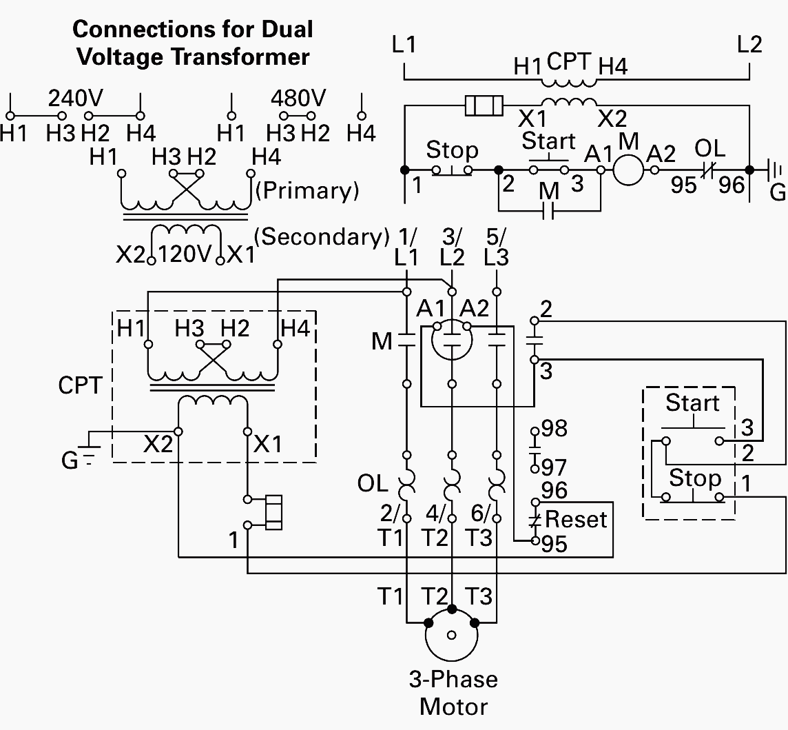
Wiring Of Control Power Transformer For Motor Control Circuits Eep from electrical-engineering-portal.com Firstly, compressor startup without load. Making sure that obstructions and blockages are kept under control or checked thoroughly. A wiring diagram is a streamlined conventional pictorial depiction of an electric circuit. Control and shutdown schemes, diagrams of plumbing systems, heating schemes, schematics of waste water disposal systems, safety and regulatory requirements, diagrams of ventilation systems, mechanical diagrams, industrial diagrams, basic start up and operational information. Measured 120 vac between points a and c, with hand/off/auto switch in the auto position. An air compressor generates power in the form of air pressure, and for an air compressor to work efficiently it requires a certain unit. Include the model number of your compressor. Every industry uses compressed air.
I'm trying to understand the control circuit for an air compressor that my company is currently using.
Air compressor capacitor wiring diagram before you call a ac there are many air conditioning and heat pump brands in the market but one common component is the compressor. Making sure that obstructions and blockages are kept under control or checked thoroughly. Different tools accomplish this in different ways. This mini audio compressor circuit use only one active component t1. I'm trying to understand the control circuit for an air compressor that my company is currently using. A technician begins diagnosing the circuit, following the steps shown (in order): Firstly, compressor startup without load. 1 an open in the air mix control motor circuit 2 a short in the air mix control motor circuit 3 a problem in the air mix control linkage, door, or motor 4 an open or short in the mode control motor circuit 5 a problem in the mode control linkage, doors, or motor 6 a problem in the blower motor circuit 7 hvac control unit internal error Trips circuit when there is a fault. Measured 120 vac between points a and c, with hand/off/auto switch in the auto position. It reveals the parts of the circuit as simplified forms, as well as the power and also signal connections between the tools. This is a common type of air compressor and is one of the easiest to take care of. A wiring diagram is a simplified traditional pictorial depiction of an electric circuit.
Every industry uses compressed air. Variety of wiring diagram for air compressor motor. This is a common type of air compressor and is one of the easiest to take care of. Air compressor system schematic diagram. There are several control methods available for air compressors, which may greatly affect the overall operating efficiency of the compressor.
Plc Compressor Control Ladder Logic Air Compressor Plc Program from instrumentationtools.com 28, 2007 — electrical circuit diagrams The air compressor context is selected on the diagram, and its nested parts and properties are displayed. This air compressor control circuit has a problem. Air compressor system schematic diagram. Regulations for noise emissions applicable to portable air compressors. The air compressor is a vital piece of equipment in almost any shop. An air compressor generates power in the form of air pressure, and for an air compressor to work efficiently it requires a certain unit. The air compressor refuses to start even when the air pressure is zero psi.
Read here to learn about inlet valve modulation / inlet throttling, load / unload (dual) control, variable displacement, variable speed, and centrifugal compressor controls.
Variety of lead lag pump control wiring diagram. Compressor noise emission control information this compressor conforms to u.s. It shows the components of the circuit as simplified shapes, and also the power and signal connections in between the tools. The air compressor is a vital piece of equipment in almost any shop. Xrhs385 md information labels ontrol and indicator panel the control and indicator panel is located behind the small panel in the front service door. It shows the parts of the circuit as simplified shapes, as well as the power as well as signal connections between the devices. Furthermore, this particular relay is controlled by the thermostat. There are several control methods available for air compressors, which may greatly affect the overall operating efficiency of the compressor. Different tools accomplish this in different ways. It reveals the parts of the circuit as simplified forms, as well as the power and also signal connections between the tools. It shows the parts of the circuit as simplified forms, and the power and signal connections in between the gadgets. A wiring diagram is a simplified standard photographic depiction of an electric circuit. Nema and iec markings and schematic diagrams.4 control and power connection table 4.
A wiring diagram is a streamlined conventional pictorial depiction of an electric circuit. A blown line, or a thrown belt can cause the compressor to run continuously until t… Control and shutdown schemes, diagrams of plumbing systems, heating schemes, schematics of waste water disposal systems, safety and regulatory requirements, diagrams of ventilation systems, mechanical diagrams, industrial diagrams, basic start up and operational information. Variety of lead lag pump control wiring diagram. This mini audio compressor circuit use only one active component t1.
Electrical Wiring Diagrams For Air Conditioning Systems Part Two Electrical Knowhow from 4.bp.blogspot.com Control features of a air compressor system is categorized. Read here to learn about inlet valve modulation / inlet throttling, load / unload (dual) control, variable displacement, variable speed, and centrifugal compressor controls. Include the model number of your compressor. A wiring diagram is a streamlined conventional pictorial depiction of an electric circuit. This is an audio compressor/agc (automatic gain control) with an astonishing 75db input voltage range. Nema and iec markings and schematic diagrams.4 control and power connection table 4. This mini audio compressor circuit use only one active component t1. The audio signal goes thru c1, r1, audio compressor circuit with ssm2165
Air compressor capacitor wiring diagram before you call a ac there are many air conditioning and heat pump brands in the market but one common component is the compressor.
The system n din rail mount contactors, fuse block, smart relay. It reveals the parts of the circuit as simplified forms, as well as the power and also signal connections between the tools. A wiring diagram is a simplified standard photographic depiction of an electric circuit. As a result, perhaps the central pneumatic air compressor owner/user family, which is a huge one, can offer advice as some of them will, undoubtedly, already dealt with the same problem you are experiencing with your hf central pneumatic air compressor. If not, the arrangement won't function as it should be. Air compressor control wiring diagram. An air compressor generates power in the form of air pressure, and for an air compressor to work efficiently it requires a certain unit. I'm trying to understand the control circuit for an air compressor that my company is currently using. 28, 2007 — electrical circuit diagrams Ontrol panel automatically alternates from compressor a to bc. Variety of wiring diagram for air compressor motor. Different tools accomplish this in different ways. Variety of lead lag pump control wiring diagram.