Home
› Car Trailer Wiring Diagram With Brakes - 7 Pin Trailer Wiring Diagram Electric Brakes | Trailer Wiring Diagram / Trailer wiring diagrams trailer wiring connectors various connectors are available from four to seven pins that allow for the transfer of power for the lighting as well as auxiliary functions such as an electric trailer brake controller, backup lights, or a 12v power supply for a winch or interior trailer lights.
Car Trailer Wiring Diagram With Brakes - 7 Pin Trailer Wiring Diagram Electric Brakes | Trailer Wiring Diagram / Trailer wiring diagrams trailer wiring connectors various connectors are available from four to seven pins that allow for the transfer of power for the lighting as well as auxiliary functions such as an electric trailer brake controller, backup lights, or a 12v power supply for a winch or interior trailer lights.
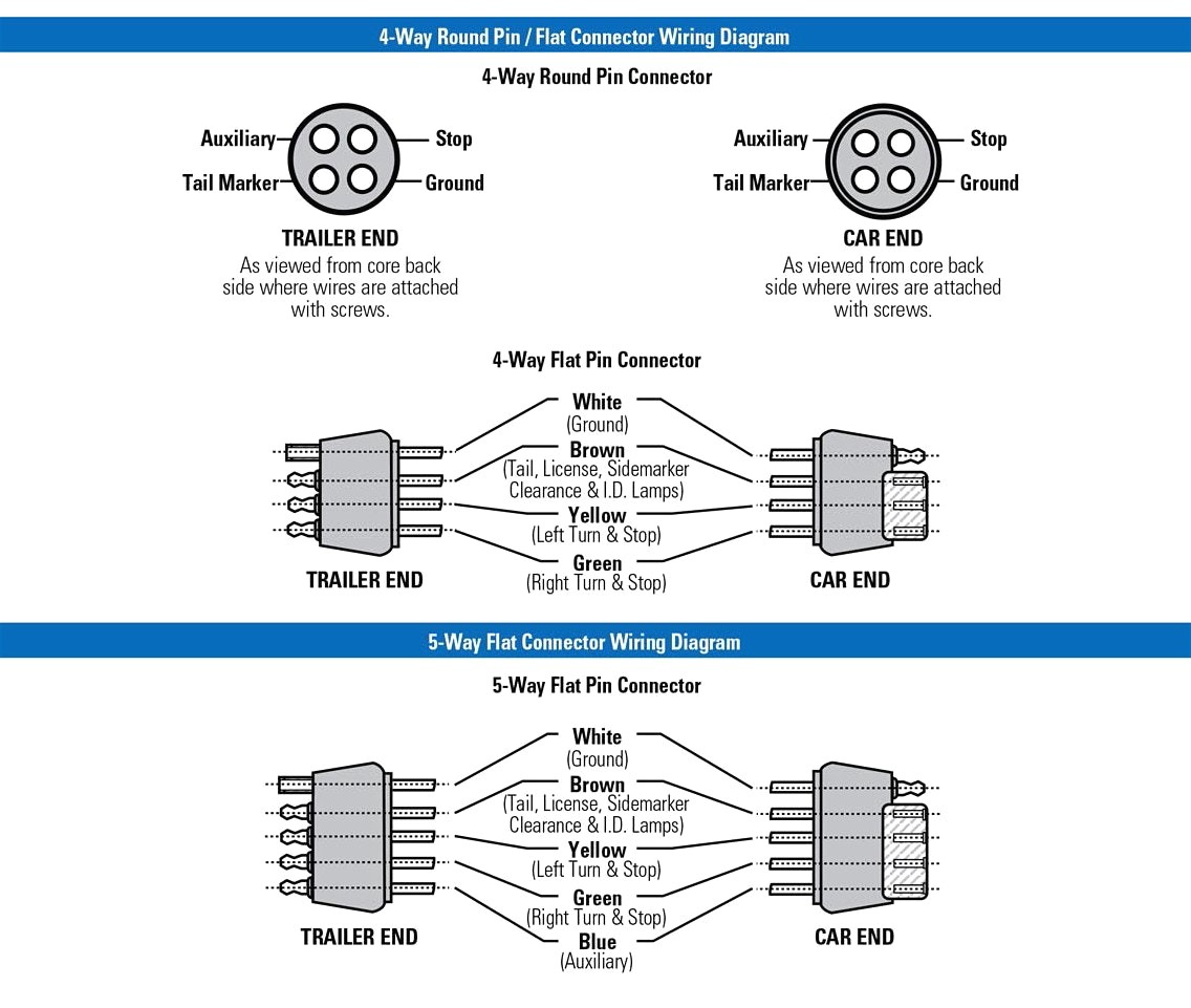
Car Trailer Wiring Diagram With Brakes - 7 Pin Trailer Wiring Diagram Electric Brakes | Trailer Wiring Diagram / Trailer wiring diagrams trailer wiring connectors various connectors are available from four to seven pins that allow for the transfer of power for the lighting as well as auxiliary functions such as an electric trailer brake controller, backup lights, or a 12v power supply for a winch or interior trailer lights.. Trailer wiring and brake control wiring. This article will be discussing utility trailer wiring diagram with brakes.what are the benefits of understanding these knowledge? The diagrams below show the typical trailer wiring for 4 pin flat connectors all the way to 7 pin round connectors. The red (stoplight) wire must be connected to the cold side of the brake pedal stoplight switch. It should not be carrying significant loads during the trip.
A wiring diagram is a simplified conventional photographic depiction of an electric circuit. When it is plugged, it disengages hydraulic trailer actuator when you reverse, so the trailer brakes are off at that moment. This type of connector is great for customer trailers. The other thing that you will get a circuit diagram could be lines. This short video is about trailer brakes, electric brakes and wiring.
Tow Vehicle Wiring Diagram Download from wholefoodsonabudget.com Or maybe a comprehensive product guide? It reveals the parts of the circuit as streamlined forms, as well as the power and signal connections in between the gadgets. Trailer wiring diagrams trailer wiring connectors various connectors are available from four to seven pins that allow for the transfer of power for the lighting as well as auxiliary functions such as an electric trailer brake controller, backup lights, or a 12v power supply for a winch or interior trailer lights. There are two things which are going to be present in almost any 7 pin trailer wiring diagram with brakes. Splice down line from the switch; The extra wire, as a rule, is used to power backup lights. A wiring diagram is a kind of schematic which uses abstract pictorial symbols showing every one of the interconnections of components in a very system. A wiring diagram is a simplified conventional photographic depiction of an electric circuit.
Circuits already present in trailers for powering standard loads including tail lights, blinkers and brake lights each have a capacity of 10 amps.
First, knowing the diagram of wires for trailer will be helpful during troubleshooting. The black wire is the power supply line to the brake control. The red (stoplight) wire must be connected to the cold side of the brake pedal stoplight switch. I go over all the basics on wiring up your vehicle trailer harness and electric brakes. The black wire is the power supply line to the brake control. There is a very fundamental car trailer wiring diagram with brakes. It shows the components of the circuit as streamlined shapes, and the power and also signal connections in between the devices. This short video is about trailer brakes, electric brakes and wiring. Special light and wiring systems need to be installed on your tow vehicle before you can tow any trailer. Assortment of electric trailer brake wiring schematic. The extra wire, as a rule, is used to power backup lights. When it is plugged, it disengages hydraulic trailer actuator when you reverse, so the trailer brakes are off at that moment. The service brake circuit must be disconnected from an existing trailer plug.
It is important to note that the white wire is the ground wire, you will notice this even when you buy lights. Elecbrakes must be connected to trailer wiring circuits as outlined in the wiring diagram. Special light and wiring systems need to be installed on your tow vehicle before you can tow any trailer. The other thing that you will get a circuit diagram could be lines. But it also means that without wiring in a separate cable to the car battery all the power that is used to activate the trailer brakes has to be drawn from the existing trailer circuits.
Trailer Wiring Diagrams | North Texas Trailers | Fort Worth from www.northtexastrailers.com This contact has chosen to use one of the connections of the iso 1724 is used for position light to electric brakes (pin 5, 58r), which means that if you connect a trailer with electric brakes to a towing vehicle. They also provide a wire for a ground connection. This short video is about trailer brakes, electric brakes and wiring. Trailer wiring connectors various connectors are available from four to seven pins that allow for the transfer of power for the lighting as well as auxiliary functions such as an electric trailer brake controller, backup lights, or a 12v power supply for a winch or interior trailer lights. It reveals the parts of the circuit as streamlined forms, as well as the power and signal connections in between the gadgets. It is important to note that the white wire is the ground wire, you will notice this even when you buy lights. The trailer lighting system must not be directly spliced into your tow. Variety of trailer breakaway wiring schematic.
Special light and wiring systems need to be installed on your tow vehicle before you can tow any trailer.
Circuits already present in trailers for powering standard loads including tail lights, blinkers and brake lights each have a capacity of 10 amps. This short video is about trailer brakes, electric brakes and wiring. A circuit is usually composed by many components. Ensure it is sealed off and cannot create a short circuit with any other wire or the chassis. The extra wire, as a rule, is used to power backup lights. It is important to note that the white wire is the ground wire, you will notice this even when you buy lights. If your brake lights work, or your marker lights work, but nothing works when you turn on both at the same time, your trailer is not grounded to the truck. Trailer side car side trailer side car side trailer side car side trailer side car side wiring plug diagram. Splice down line from the switch; Installing new trailer brakes on a tanden axle trailer.when wiring my understanding is that the existing 7 pole wiring can be tapped into by running a two wire 12 guage section from brake to brake and then splicing into the existing 7 ptong and attaching the blue and whiteground wires.do i have to ground the white wire to the trailer ? Looking for a wiring diagram? Horse trailer, travel trailers, landscaping trailer, car trailer, etc. The trailer wiring diagram shows this wire going to all the lights and brakes.
Variety of trailer breakaway wiring schematic. Wiring plug diagram created date: A circuit is usually composed by many components. Splice down line from the switch; A lot of led lights come with black and white wires and people can easily confuse the black wire for the ground.
Trailer Wiring Diagram Australia 7 Pin Flat | Trailer Wiring Diagram from trailer-wiring-diagram.com Check with a test light or vom. A circuit is usually composed by many components. Check out our download center here for all of your product support needs. This type of connector is great for customer trailers. A wiring diagram is a kind of schematic which uses abstract pictorial symbols showing every one of the interconnections of components in a very system. Installing new trailer brakes on a tanden axle trailer.when wiring my understanding is that the existing 7 pole wiring can be tapped into by running a two wire 12 guage section from brake to brake and then splicing into the existing 7 ptong and attaching the blue and whiteground wires.do i have to ground the white wire to the trailer ? The red (stoplight) wire must be connected to the cold side of the brake pedal stoplight switch. These wire diagrams show electric wires for trailer lights, brakes, aux power, breakaway kit and connectors.
Assortment of electric trailer brake wiring schematic.
It shows the components of the circuit as streamlined shapes, and the power and also signal connections in between the devices. The black (sometimes red) 12v and blue electric brakes wire may need to be reversed to suit the trailer. The extra wire, as a rule, is used to power backup lights. Trailer side car side trailer side car side trailer side car side trailer side car side wiring plug diagram. So, if you step on the brakes and all the trailer lights go out, then you need to ground your trailer to your truck with the ground wire. Splice down line from the switch; It should not be carrying significant loads during the trip. The trailer lighting system must not be directly spliced into your tow. It reveals the parts of the circuit as streamlined forms, as well as the power and signal connections in between the gadgets. The black wire is the power supply line to the brake control. Splice down line from the switch; The blue (brake output) wire must be connected to the trailer connector's brake wire. A wiring diagram is a streamlined conventional pictorial representation of an electric circuit.