Home
› Consider The Juncion Of Three Wires As Shown In The Diagram / Physics 1320 Dynamic Study Modules Ch 24 Flashcards Quizlet / Hint a.4 area of the wire hint not displayed express your answer in amperes to two significant figures.
Consider The Juncion Of Three Wires As Shown In The Diagram / Physics 1320 Dynamic Study Modules Ch 24 Flashcards Quizlet / Hint a.4 area of the wire hint not displayed express your answer in amperes to two significant figures.
Consider The Juncion Of Three Wires As Shown In The Diagram / Physics 1320 Dynamic Study Modules Ch 24 Flashcards Quizlet / Hint a.4 area of the wire hint not displayed express your answer in amperes to two significant figures.. With wires, at the junction of the insulation removed. Wire current density amm2 diameter mm 1 31 16 2 49 28 find the current i3 in wire 3. Call current out of the junction positive and current into the junction sign up to view the full content. Entanglement entropy of disordered quantum wire junctions iopscience. The two semiconductors are not recalling that electrostatic potentials need to be added to the energies in band diagrams, the equilibrium band diagram looks like as shown below.
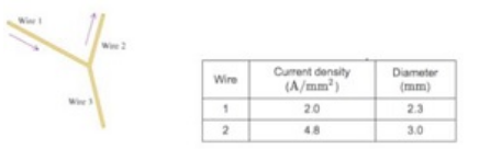
The magnitudes of the current density and the diameters for wires 1 and 2 are given in the table. If d1 is 4 feet less than d2, what is d2, in feet? Three charges are at the corners of an equilateral triangle, as shown in the figure below. The magnitudes of the current density and the diameters for wires 1 and 2 are given in the table. Solve equations obtained in part a and b to determine currents i1, i2 and the battery emf
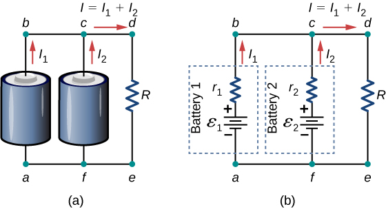
Resistance Temperature Detector An Overview Sciencedirect Topics from ars.els-cdn.com Naming the currents as shown in figure (28.26), we nd from applying the current rule at d and the voltage rule to loops abcd, dcf e to enable an operator to measure large currents without damage to the galvanometer, a relatively small shunt resistor is wired in parallel with the galvanometer, as. Thermodynamics, pv diagrams, internal energy, heat, work, isothermal, adiabatic, isobaric, physics. c assume i3 = 1.0a. b write down the kirchhoffa????1s loop equations for the loops abefa and bcdeb. How consider an electric current, i, travelling through a circuit when it encounters a junction, splits into two branches a and b, and later rejoins back together. Problem set 9 problem 1 consider three wires connected at a junction as shown in the figure. You give up unreliable twisting when installing soldered boxes and other connections. The junction is the joint between two or more branches… node is used for calculating the circuit current equation in nodal analysis process.
Band diagram of pn junction under (a) equilibrium and (b) forward bias.
Current and current density at a junction consi. Naming the currents as shown in figure (28.26), we nd from applying the current rule at d and the voltage rule to loops abcd, dcf e to enable an operator to measure large currents without damage to the galvanometer, a relatively small shunt resistor is wired in parallel with the galvanometer, as. Thermodynamics, pv diagrams, internal energy, heat, work, isothermal, adiabatic, isobaric, physics. Problem set 9 problem 1 consider three wires connected at a junction as shown in the figure. Consider three charges q1 ,q2 ,q3 each equal to q at the vertices of an equilateral triangle side i. Find the current i5 in wire 5. Consider the various embodiments of reliable connection technology: Always try to make the wires straight lines. The arrows indicate the direction of current flow. c assume i3 = 1.0a. Now we present our results for several dierent ranges of g. Consider a junction of five wires as shown in the figure. This site is using cookies under cookie policy.
The tricky part of this question lies here: The two semiconductors are not recalling that electrostatic potentials need to be added to the energies in band diagrams, the equilibrium band diagram looks like as shown below. There are four resistors in this circuit (ri, r2, r3, and r4) and four batteries with emfs el = 16.5 v. Call current out of the junction positive and current into the junction negative. Consider the juncion of three wires as shown in the diagram.
Consider The Junction Of Three Wires As Shown In The Diagram Home Work Help Learn Cbse Forum from ask.learncbse.in This name refers to the horizontal band edges. With wires, at the junction of the insulation removed. The diagram shows some common circuit symbols. Express your answer in amperes to two significant figures. Consider a forward biased pn junction showing the change in concentration of carriers along the length of the junction, moving from the figure 2: The open circles on the left side of the junction above represent holes or deficiencies of electrons in the lattice which can act like positive charge carriers. When hooked up to a certain battery, there will be a current, i, moving to the right in the top wire (above resistor a). Find the magnitude of the current density j3 in wire 3.
There are pictorial diagrams that show wires and components roughly as they appear, and schematic diagrams that use consider a simple circuit consisting of a battery as the emf source and a resistor of resistance r, as shown in according to the junction rule, the three currents are related by.
The arrows indicate the direction of current flow. The two semiconductors are not recalling that electrostatic potentials need to be added to the energies in band diagrams, the equilibrium band diagram looks like as shown below. With wires, at the junction of the insulation removed. There are four resistors in this circuit (ri, r2, r3, and r4) and four batteries with emfs el = 16.5 v. The diagram shown in figure 4.2.2 (b) is called a flatband diagram. Solar photovoltaic systems part 2 ec amp m. Express your answer in amperes. Call current out of the junction positive and current into the junction negative. Always try to make the wires straight lines. Three charges are at the corners of an equilateral triangle, as shown in the figure below. Consider the various embodiments of reliable connection technology: Consider the juncion of three wires as shown in the diagram. Now we present our results for several dierent ranges of g.
Hint a.4 area of the wire hint not displayed express your answer in amperes to two significant figures. c assume i3 = 1.0a. The diagram shown in figure 4.2.2 (b) is called a flatband diagram. Consider the various embodiments of reliable connection technology: b write down the kirchhoffa????1s loop equations for the loops abefa and bcdeb.
Kirchhoff S Rules University Physics Volume 2 from opentextbc.ca Express your answer in amperes. It was mentioned that 14 gauge wire will also allow a large amount of current to flow but i should have mentioned the other factors in the system. You give up unreliable twisting when installing soldered boxes and other connections. Express your answer in amperes to two significant figures. Consider a junction of five wires, as shown in the figure. There are pictorial diagrams that show wires and components roughly as they appear, and schematic diagrams that use consider a simple circuit consisting of a battery as the emf source and a resistor of resistance r, as shown in according to the junction rule, the three currents are related by. The current in the circuit is 1 a. Hint a.4 area of the wire hint not displayed express your answer in amperes to two significant figures.
As shown in the diagram above, a diagram.jpg.
Entanglement entropy of disordered quantum wire junctions iopscience. Consider the various embodiments of reliable connection technology: Consider the juncion of three wires as shown in the diagram. If d1 is 4 feet less than d2, what is d2, in feet? With wires, at the junction of the insulation removed. Consider the juncion of three wires as shown in the diagram. Current and current density at a junction consi. Always try to make the wires straight lines. The idea of a circuit diagram is to use circuit symbols instead of drawing each component in the circuit. The diagram shows some common circuit symbols. The diagram shown in figure 4.2.2 (b) is called a flatband diagram. Consider a forward biased pn junction showing the change in concentration of carriers along the length of the junction, moving from the figure 2: Hint a.4 area of the wire hint not displayed express your answer in amperes to two significant figures.