Home
› Wiring Two Outlets In One Box Diagram / Different Types Of Electrical Outlets And How They Work : Wiring connections in switch, outlet, and light boxes.
Wiring Two Outlets In One Box Diagram / Different Types Of Electrical Outlets And How They Work : Wiring connections in switch, outlet, and light boxes.
Wiring Two Outlets In One Box Diagram / Different Types Of Electrical Outlets And How They Work : Wiring connections in switch, outlet, and light boxes.. To add an additional outlet to the combo device, simple connect the line, neutral and ground terminals as shown in the fig below. Wiring a gfci receptacle is a little more complicated than hooking up a regular outlet but easily learned once explained. Wiring two outlets in one box in this diagram, two duplex receptacle outlets are installed in the same box and wired separately to the source using pigtails spliced to connect the terminals of each one. With this kind of an illustrative guide, you will have the ability to troubleshoot, stop, and full your projects without difficulty. Wiring outlets together using the device terminals, instead of a pigtail splice as shown in the next diagram, can create a weakest link problem.
The other cable goes to the next outlet in the chain. The following house electrical wiring diagrams will show almost all the kinds of electrical wiring connections that serve the functions you need at a variety of outlet, light, and switch boxes. Attach the black wire to the bottom brass lug on the outlet. Any break or malfunction in one outlet will cause all the other outlets to fail. When an outlet receptacle is located in the middle of a circuit run—with other receptacles upstream and additional receptacles downstream—there are two ways to wire the receptacle.
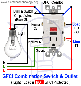
How To Wire Gfci Combo Switch Outlet Gfci Switch Outlet Wiring from www.electricaltechnology.org If you are replacing an existing gfci outlet with a new one we suggest that you read our page about replacing a gfci outlet. The wiring diagram above shows how switched outlets are often wired. Wiring diagram for multiple switched outlets. Wiring a gfci receptacle is a little more complicated than hooking up a regular outlet but easily learned once explained. In the above room electrical wiring diagram i shown a electric board in which i shown two outlets 3 one way switches and one dimmer switch. One of the cables is the live cable that either comes from another device that has power or directly from the panel. The other cable goes to the next outlet in the chain. When an outlet receptacle is located in the middle of a circuit run—with other receptacles upstream and additional receptacles downstream—there are two ways to wire the receptacle.
Wiring multiple outlets in a series in this diagram wall outlets are wired in a row using the terminal screws to pass voltage from one receptacle to the next.
Wire or rewire multiple outlets in one box. Attach the black wire to the bottom brass lug on the outlet. One of the most common wiring configurations your going to find with outlets are shown in the diagram below. Diagram for parallel or series. Wiring diagram for multiple switched outlets. The box fill will be fine in a double gang with only 2 devices and 2 sets of #12. Wiring outlets together using the device terminals, instead of a pigtail splice as shown in the next diagram, can create a weakest link problem. To wire multiple outlets, follow the circuit diagrams posted in this article. If you are replacing an existing gfci outlet with a new one we suggest that you read our page about replacing a gfci outlet. I need to run multiple outlets off of one breaker. Wiring outlets has to be done in parallel, since that way, should one outlet fail or a bulb inserted in one light fixture burn out, the rest of the fixtures and appliances hooked up to that same line will keep working. The diagram below shows the power entering the circuit at the grounded outlet box location, then sending power up to the switch and a switched leg back down to the outlet. Pull the cable through a hole in the back of the electrical box, separate the wires and strip an inch of insulation off the end of each one.
Multiple outlet in serie wiring diagram : Start by wiring the first receptacle to the live circuit cable. The other cable goes to the next outlet in the chain. How to wire gfci outlets. These electrical wiring diagrams show typical connections.
Tracing 3 Wire Circuits Jlc Online from cdnassets.hw.net Diagram for parallel or series. You can also learn about wiring gfci outlets in the following 7 steps. Wiring connections in switch, outlet, and light boxes. Wiring outlets together using the device terminals, instead of a pigtail splice as shown in the next diagram, can create a weakest link problem. Wiring outlets has to be done in parallel, since that way, should one outlet fail or a bulb inserted in one light fixture burn out, the rest of the fixtures and appliances hooked up to that same line will keep working. In my case i'm doing it so that i can have more power available on the. These electrical wiring diagrams show typical connections. To wire multiple outlets, follow the circuit diagrams posted in this article.
Diagram for parallel or series.
You can also learn about wiring gfci outlets in the following 7 steps. Start by wiring the first receptacle to the live circuit cable. Does anyone have a wiring diagram to help reassure me i am doing it correctly? Pull the cable through a hole in the back of the electrical box, separate the wires and strip an inch of insulation off the end of each one. In my case i'm doing it so that i can have more power available on the. Wire or rewire multiple outlets in one box. Wiring outlets together using the device terminals, instead of a pigtail splice as shown in the next diagram, can create a weakest link problem. In the above room electrical wiring diagram i shown a electric board in which i shown two outlets 3 one way switches and one dimmer switch. Wiring multiple outlets in a series in this diagram wall outlets are wired in a row using the terminal screws to pass voltage from one receptacle to the next. The following house electrical wiring diagrams will show almost all the kinds of electrical wiring connections that serve the functions you need at a variety of outlet, light, and switch boxes. If you're wiring an outlet in the middle of a chain of outlets, you'll have two cables in the outlet box. These electrical wiring diagrams show typical connections. Note that this a simple wiring instillation diagram for one room in which i shown the wiring connection of two light bulbs and one ceiling fan connection.
There are two basic options for wiring the receptacle to the two cables running through the box. I need to run multiple outlets off of one breaker. One of the most common wiring configurations your going to find with outlets are shown in the diagram below. When an outlet receptacle is located in the middle of a circuit run—with other receptacles upstream and additional receptacles downstream—there are two ways to wire the receptacle. With this kind of an illustrative guide, you will have the ability to troubleshoot, stop, and full your projects without difficulty.
Split Combo Device With Second Receptacle Light Switch Wiring Wiring A Plug Home Electrical Wiring from i.pinimg.com I want to make sure i do it right so i don't cause a volt drop when two ballasts fire up. In the above room electrical wiring diagram i shown a electric board in which i shown two outlets 3 one way switches and one dimmer switch. You can also learn about wiring gfci outlets in the following 7 steps. In my case i'm doing it so that i can have more power available on the. This size breaker requires a minimum of a #10 gauge wire so this wire used would be a 10/2 with ground. Diagram for parallel or series. Any break or malfunction in one outlet will cause all the other outlets to fail. The wiring diagram above shows how switched outlets are often wired.
If you're wiring an outlet in the middle of a chain of outlets, you'll have two cables in the outlet box.
Wiring a gfci receptacle is a little more complicated than hooking up a regular outlet but easily learned once explained. In the above room electrical wiring diagram i shown a electric board in which i shown two outlets 3 one way switches and one dimmer switch. This electrical wiring question came from larry, in nokomis, florida. This will provide independent gfci protection for the outlet that has no other devices and the one that feeds other devices. In this wiring diagram, the builtin switch in the combo device controls a lighting point whereas, outlet can be used for other loads. Multiple outlet in serie wiring diagram : In my case i'm doing it so that i can have more power available on the. Wiring connections in switch, outlet, and light boxes. Outlet wiring for a table lamp or a floor light fixture. To wire multiple outlets, follow the circuit diagrams posted in this article. Connect the white wire to the bottom silver lug in the same way. With each outlet connected by its own pigtail wire, if one fails because of physical damage, the other won't be affected and should still work. Wiring outlets has to be done in parallel, since that way, should one outlet fail or a bulb inserted in one light fixture burn out, the rest of the fixtures and appliances hooked up to that same line will keep working.